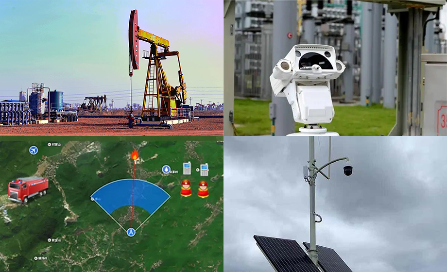
10 km wireless module large oil field/forest fire digital transmission acquisition program, video monitoring can bring intuitive and visual effects to the construction units or institutions. Widely used in warehouse monitoring and other occasions, important traffic and other important forestry road monitoring, water conservancy, oil field, tunnel, coal mine, border defense and other important positions of video monitoring. 10 km wireless module wireless monitoring You can sit in your office and see real-time images of your organization on important occasions; Do not leave the office can also deal with various on-site emergencies, monitoring the whole process of event processing, see the on-site image effect after processing.

1, 10 km wireless module wireless video monitoring technology introduction
Wireless video monitoring digital signal, based on analog signal processing, through microwave transmission to achieve signal exchange, control, video storage and playback on demand, through the establishment of a powerful central business platform, the system to achieve all decoding equipment and video storage equipment unified management and centralized control. Users only need to log in to the central service platform to realize unified invocation, browsing, and use of monitoring resources across the entire network.
Ii. Customer on-site analysis
The site is located in a large oil field production site, and the oil field equipment works 24 hours a day. In order to ensure the smooth progress of mining and the safety of the oil storage tank and equipment, the video surveillance scheme is adopted for 24 hours monitoring and video recording. It will be transmitted to the headquarters 6 kilometers away to watch, and emergencies can be handled in time. Considering the long transmission distance, we use 10 km wireless module wireless video transmission equipment for remote wireless transmission, wireless transmission of high-definition video pictures.
Three, 10 km wireless module wireless transmission solution
The back-end control room is located 6km away and customers pass through the monitoring center. NVR monitoring video, real-time viewing of the front segment HD pictures, and through two-way voice contact with the front segment duty personnel.
10 km wireless module is a wireless communication scheme for oil field digital transmission collection. The oil field production plant consists of multiple oil Wells, measuring stations, manifold valve groups, oil transfer stations, joint stations, crude oil transport system, oil tanks and other scattered facilities in the oil field. The working status and oil recovery data (mainly including temperature), pressure and flow rate of various facilities of the entire oil production plant are obtained. It is directly related to the stability of oilfield production and the quality of crude oil.
At present, most of the workers regularly check the operation of the equipment and collect oil recovery data every day. Due to the large number of oil Wells, the distribution range from tens to hundreds of square kilometers inevitably increases the labor intensity of workers, affects the real-time and even accuracy of equipment monitoring and oil recovery data, and has hidden dangers such as clerical errors.
As the manual record collection speed is slow, the upper layer cannot know the real situation of the site in time. Therefore, more effective and flexible processing solutions are needed. Therefore, the automation, traditional management mode and manual data recording mode of oilfield can not meet the development requirements of modern enterprises. To realize the real-time acquisition and data analysis of field data and equipment information, remote command and control equipment is a suitable choice.
Our 10 km wireless module has the characteristics of long transmission distance, good real-time performance and high cost performance. It is recommended to use the equipment TY-0.5A-YK waiting wireless transmission equipment in oilfield acquisition.
10 km wireless module advantages:
Frequency range: 2.3~2.384GHz, 2.4~2.484GHz, 5.8GHz
Interface mode SDIO (SDIO 1.1/2.0/3.0)
IEEE standard: IEEE 802.11b/g/n/LR-WiFi
LR-WiFi supports large data transmission over long distances
Stamp hole
Operating voltage: 3.3V±0.2V, VDIO 3.3±0.2V or 1.8±0.18V, SDIO signal level range 1.8V~3.3V.
10 km wireless module forest fire wireless video transmission solution
I. Site Description:
The distance between monitoring point No. 2 and monitoring point No. 1 is 8.3 kilometers; The distance between the No. 1 monitoring point and the monitoring center is 20 kilometers; The distance between monitoring point No. 3 and monitoring point No. 4 is 6 kilometers; The distance between monitoring point 6 and monitoring point 5 is 3 kilometers; The distance between monitoring point No.5 and monitoring point No. 4 is 3.5 kilometers; The distance between the No. 4 monitoring point and the monitoring center is 15 kilometers.
2. Customers' specific requirements for wireless video surveillance transmission equipment
As humanity enters the age of high technology, the speed of urban development is combined with technology, but with the development of technology, human destruction and destruction is also on the rise. High technology is needed to maintain the combination of environmental destruction. Forest fire prevention monitoring has become an indispensable protection measure for natural environment reserves. The use of forest fire monitoring system can greatly reduce the destruction of forest trees and solve the on-site problems in time.
Iii. Design idea of wireless video monitoring engineering scheme of 10km wireless module:
According to customer demand, our company designed a set of advanced digital wireless video surveillance system. The whole system adopts our company's 2.4/5.8G band industrial grade digital wireless video transmission.
1.2 The No. 1 monitoring point is transmitted to the No. 1 monitoring point through a module, which is received (one-to-one) one by one, and then transmitted to the monitoring center through a receiver (one-to-one);
2.3 The No. 4 monitoring point is transmitted to the No. 4 monitoring point one by one, receiving (one-to-one);
3.6 Monitoring point No.5 is transmitted to monitoring point No.5 through one transmitter, which is received (one-to-one) one by one, and then transmitted to monitoring point No.4 through one receiver (one-to-one);
4.4 Monitoring point No. 3, No. 5 and No. 6 images are integrated and sent to the monitoring center one by one through the images of monitoring point No. 6.


